Crane Road and Structure Engineering: How We Plan for Accuracy and Durability
The crane track is the "rail system" of production: its geometry, rigidity and connection to the supporting structure determine smooth movement, safety and maintenance costs. A well-designed and measured crane track reduces sway, wear on wheels and rails, energy consumption and unplanned stops.
What determines the quality of the crane path?
- Geometry and alignment: straightness, parallelism of the rails, elevations (cross/longitudinal level), permissible switches/distortions.
- Hardness and deformations: deflections of beams/cantilevers under characteristic loads; local sagging and “soft” supports.
- Peak and dynamic loads: braking/acceleration forces, lateral horizontal forces, impact loads in buffers and limit switches.
- Temperature influences: rail and beam expansion joints, expansion joints, anti-seize slides and bearings.
- Connection and supports: vibration isolation/pads, type of fixation (terminals, anchor bolts), quality of seams and fasteners.
Rails, wheels and contact pair
- Profile and steel selection: rail/sleeper profile according to load and wheel pressures; hardness and wear resistance.
- Cross-sections and connections: rail lengths, type of butt joints, base plates, support continuity.
- Wheels and guides: elastokinematics, taper/crown, force distribution; limiting skewing (flooding/wedge effect).
- Lubrication and cleanliness: lubrication (where permissible), drainage/cleaning of dust and chips.
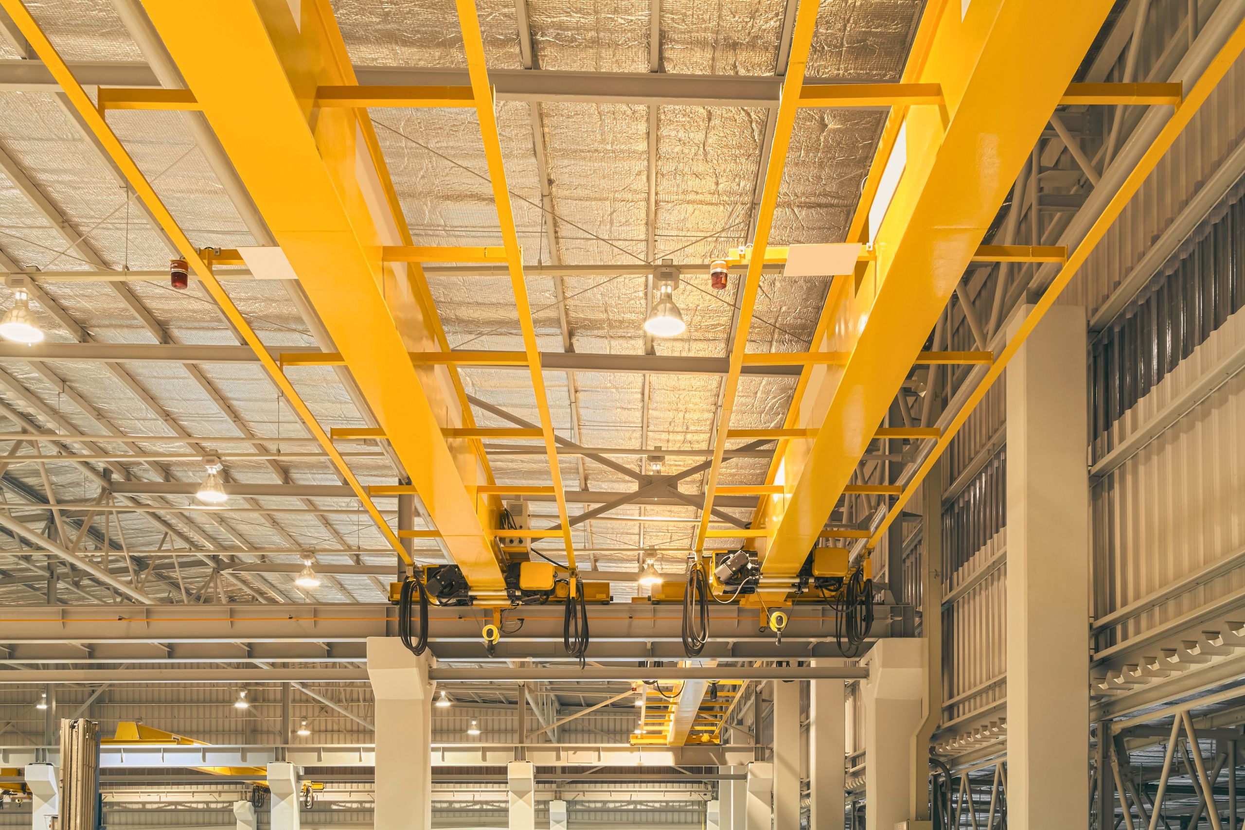
Supporting structure and foundation
- Beams and columns: selection of profiles, connections and ribs to limit torsion/vibration; checking of nodes for fatigue.
- Foundations: foundation deformations, various settlements, anchoring and crack control.
- Hiking trails and services: inspection access, railings, fall/belay points.
Geometry control: tools and tolerances
- Measurement methods: total station/laser tracker, levels and wire measures; repeatable base points.
- Monitoring parameters: horizontal/vertical deviations in length, difference in rail heights (cross level), gauges to facilities.
- When to measure: before installation, after pre-loading, after 72 hours of "calming", after first cycles, periodically in operation.
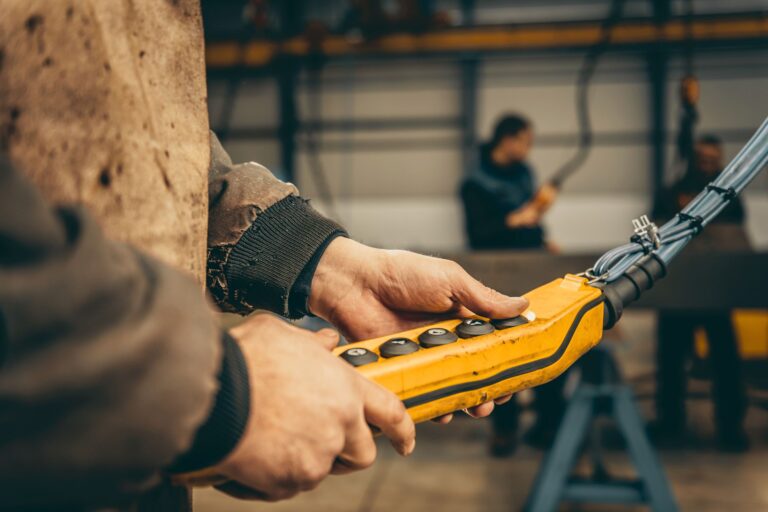
Integration with crane control
- Anti-swing and motion profiles: Smoother accelerations/brakes reduce horizontal forces on the rails.
- Zoning and soft limits: avoiding sensitive areas, limit switches with buffers.
- Monitoring: cycle counter, gearbox temperatures and current peaks as an indirect indicator of geometric problems.
Typical causes of problems (and how to avoid them)
- Local "pockets" of height → load redistribution, tire wear: requires local leveling/pads.
- Insufficient rigidity of the beams → vibrations, resonances and micro-oscillations: dimensioning for deflection and checking of natural frequencies.
- Rigid fixations without dilation → thermal stresses: expansion joints and sliding joints.
- Inaccurate rail joints → “steps” and impact loads: milled butt joints and correct tightening.
- Skewing of the bridge → increased lateral forces and wear: correction of wheelbases, guides and steering.
Design and implementation plan (phased)
- Pre-project audit: process flow, masses/cycles, environment; basic measurements of elevations and vibrations.
- Conceptual model: diagrams of beams/supports, rails, joints and anchors; evaluation of deformations and dynamics.
- Working project: details of connections, pads, retainers, buffers; specification of installation measurements.
- Installation and surveying: sequence, intermediate acceptances, height/parallelism adjustments.
- Start-up and acceptance tests: test loads, geometry protocols, basic KPIs.
- Operational monitoring: periodic measurements, maintenance log and wheel/rail wear.
Sustainability and process KPIs
- Parallelism/height deviations (mm/m or mm of full spring).
- Wear rate on wheels/rails (mm/1000 cycles).
- Unplanned downtime and reasons, as well as MTBF/MTTR.
- Energy consumption of movement (kWh/cycle) and peak currents.
- Alarm frequency (overload, limit switches, temperatures).
Final accent
A well-designed crane track is an investment in reliability: precise geometry, adequate stiffness and planned expansion reduce dynamic forces and protect the wheel-rail contact pair. The combination of structural design, correct fixing and controlled movement profiles leads to quieter, more stable and energy-efficient cycles.
Our approach is pragmatic: we start with a measurable baseline, model critical nodes, and plan a realistic sequence for installation and acceptance. This builds a sustainable infrastructure that maintains accuracy and safety throughout the entire life cycle of lifting operations.